UHZ-801G Jacketed thermal insulation magnetic flap (column) level gauge
UHZ-801G Jacketed thermal insulation magnetic flap (column) level gauge
Product descriptionUHZ-801G jacketed thermal insulation magnetic flap (column) level gauge, jacket forms are: steam
Product Details
Product description
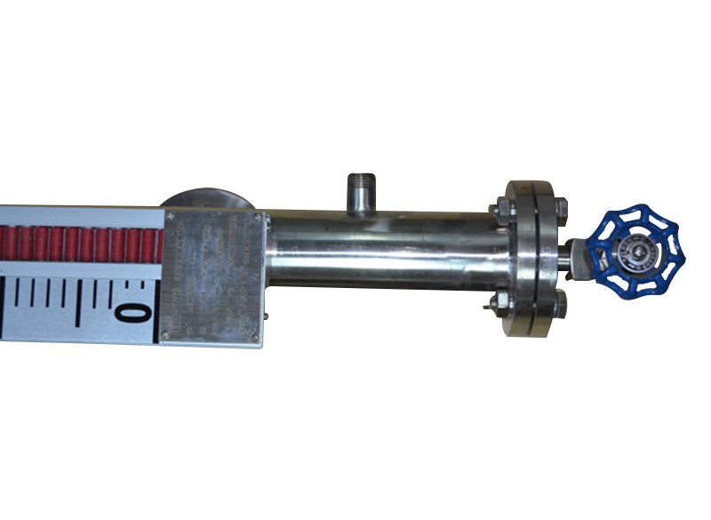
UHZ-801G jacketed thermal insulation magnetic flap (column) level gauge, jacket forms are: steam jacket, hot water circulation jacket, vacuum jacket. The series of products can achieve high sealing, anti-leakage and safe and reliable liquid level measurement under high temperature, high pressure, high viscosity and strong corrosive conditions. The level alarm and control switch can realize the upper and lower limit alarms of the liquid level or the boundary level. With the LB type liquid level transmitter, the liquid level and boundary level signals can be converted into two-wire 4~20mA, 24V.DC standard signals , to achieve long-distance detection, indication, recording and control. The series of products are widely used in petroleum, chemical, electric power, medicine, environmental protection, metallurgy, water treatment and other industries.
Structural Principles
The liquid level gauge is based on the principle of buoyancy and magnetic coupling. When the liquid level in the container under test rises and falls, the float in the main pipe of the liquid level gauge also rises and falls, and the permanent magnet steel in the float is transmitted to the field indicator through magnetic coupling, driving the red and white flipping bamboo = column or flipping plate to flip. 180°, when the liquid level rises, the column or plate turns from white to red, and when the liquid level drops, the column or plate turns from red to white, red indicates liquid phase, white indicates gas phase, and the indicator red , The white boundary is the actual height of the medium liquid level in the container, so as to realize the liquid level indication.
Basic parameters
Measuring range L: 200~8000mm
Measurement accuracy: ±5mm
Working temperature: -180℃-480℃
Working pressure: 0.6-40.0MPa
Media density: 0.6-2.0 g/cm3
Flange: DN15 DN20 DN25 RF
Flange standard: HG20592--20635-2009
Other flange standard please specify
Jacket interface: DN15 DN20 DN25 BF or G1/2" External thread other standards, please indicate the user
Material: Bypass: 304; 316L;
Float: 304; 316L; Aluminum; Titanium;
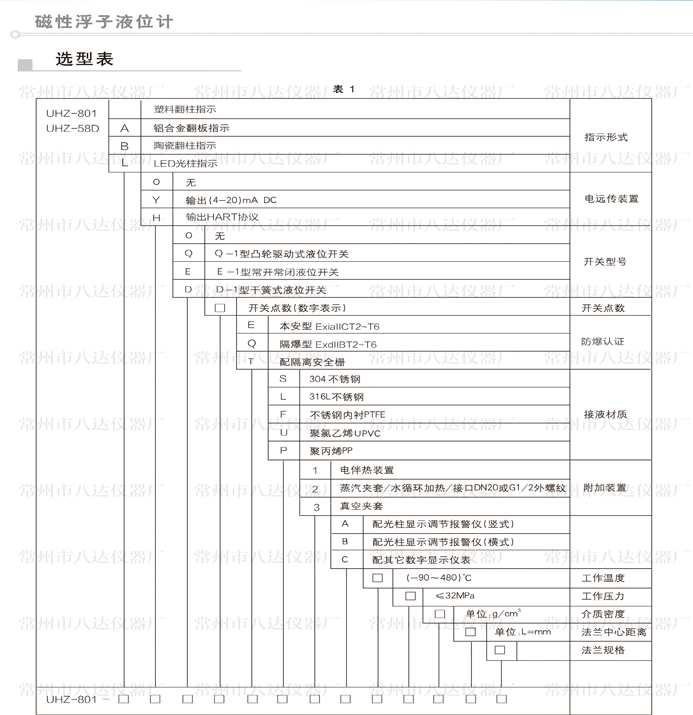
For detailed configuration, please refer to the selection table

Install and use
1. First, check whether the data on the liquid level gauge is in line with the order requirements. There must be no magnets and other magnetic substances within 200mm of the liquid level gauge, otherwise it will affect the normal operation of the liquid level gauge.
2. A shut-off valve should be installed between the liquid level gauge and the container, so as to cut off the material during maintenance and cleaning. The installation of the body must be vertical, and the maximum deflection angle is ≤3°. When the measurement range is greater than 4m, the intermediate support point should be added during installation and use.
3. Before the liquid level gauge enters into operation, the upper flange gas phase valve should be opened first, and then the lower flange night phase valve should be opened slowly, so that the medium slowly flows into the cylinder, so that the magnetic flip column can track the instructions one by one, and use the adjusting screw Adjust the zero level.


